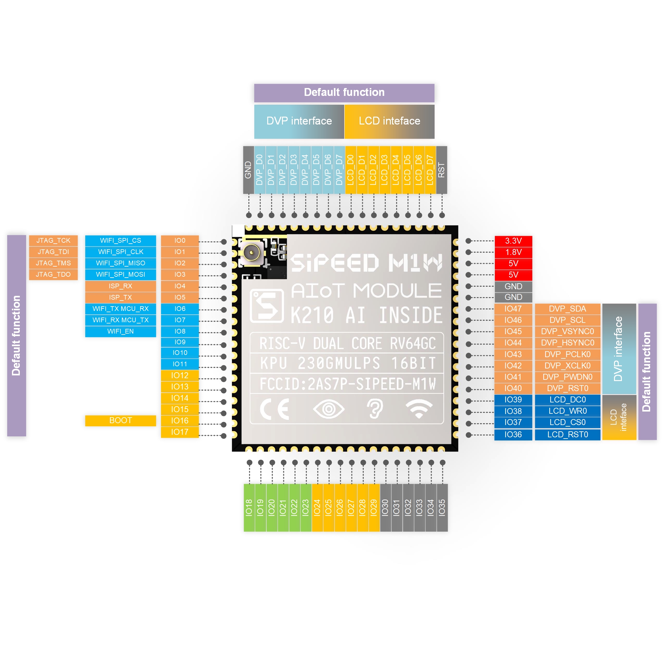
The screen is controlled by the ILI9341 controller. The goal is to have a framebuffer in memory which is pushed to the screen at a desent fps. The 8-bit interface is being used. This means we can write 1 pixel per message. The most code of the configuration and startup is based of the Adafruit TFTLCD-library.
There are a few parts to realize the desired goal:
- Screen initialization
- Creating a framebuffer in the main loop for easy testing
- Make a routine for the second core to put a framebuffer to the screen.
- Make a few basic functions so the main loop can change the framebuffer (setPixel, fillScreen, drawRect)
- Optimize the routine (Depends on how addressing works. Maybe only push pixel that changed. In that case maybe two framebuffers for comparisons?)
There are also a few thing that will be handled later on:
- More complex functions like more complex shapes
- Image displaying.
- Etc.
Screen initialization
The screen initialization consists of two things: pin configuration and the actual screen initialization. Although there is a LCD section in the pinout of the M1w module I am not going to use those pins. The problem with those pins is that they are 1.8 volts. Because the screen uses 3.3 volts and the screen interface will operate at quite a high speed. I will going to use some other pins. To be precise IO36 to IO47. Where IO36 to IO39 are used for the control and IO40 to IO47 are used for the data. The pins IO36 to IO47 are all GPIOHS pins(GPIOHS20 to GPIOHS31).
For the test I am using a MAIX bit. The pins will be changed later in the code to the pins above. For now I will use the pins IO28 to IO35 for data and IO22 to IO25 for control

Pin configuration
First we need to define the pin definitions for the screen. This will be placed in the include/screen.h file.
// Control pin definitions
#define SCREEN_GPIOHS_PIN_RD 6
#define SCREEN_GPIOHS_PIN_WR 7
#define SCREEN_GPIOHS_PIN_CD 8
#define SCREEN_GPIOHS_PIN_CS 9
#define SCREEN_IONUMBER_PIN_RD 22
#define SCREEN_IONUMBER_PIN_WR 23
#define SCREEN_IONUMBER_PIN_CD 24
#define SCREEN_IONUMBER_PIN_CS 25

// Data pin definitions
#define SCREEN_GPIOHS_PIN_DATA0 12
#define SCREEN_GPIOHS_PIN_DATA1 13
#define SCREEN_GPIOHS_PIN_DATA2 14
#define SCREEN_GPIOHS_PIN_DATA3 15
#define SCREEN_GPIOHS_PIN_DATA4 16
#define SCREEN_GPIOHS_PIN_DATA5 17
#define SCREEN_GPIOHS_PIN_DATA6 18
#define SCREEN_GPIOHS_PIN_DATA7 19
#define SCREEN_IONUMBER_PIN_DATA0 28
#define SCREEN_IONUMBER_PIN_DATA1 29
#define SCREEN_IONUMBER_PIN_DATA2 30
#define SCREEN_IONUMBER_PIN_DATA3 31
#define SCREEN_IONUMBER_PIN_DATA4 32
#define SCREEN_IONUMBER_PIN_DATA5 33
#define SCREEN_IONUMBER_PIN_DATA6 34
#define SCREEN_IONUMBER_PIN_DATA7 35
To init the pins I made a nice little function to compress the init GPIO function. this function will be placed inside of the src/gpio.c file.
void GPIO_initPinHSAsOutput(int IONumber, uint8_t GPIOHS_Pin, gpio_pin_value_t defaultValue) {
  fpioa_set_function(IONumber, FUNC_GPIOHS0 + GPIOHS_Pin);
  gpiohs_set_drive_mode(GPIOHS_Pin, GPIO_DM_OUTPUT);
  gpiohs_set_pin(GPIOHS_Pin, defaultValue);
}
Finally we need to actually init the GPIO pins. For this we call the GPIO_initPinHSAsOutput function for all the control and data pins. This function will be placed inside the src/screen.c file.
void SCREEN_initGPIO(void) {
  GPIO_initPinHSAsOutput(SCREEN_GPIOHS_PIN_RD, SCREEN_IONUMBER_PIN_RD, GPIO_PV_LOW);
  GPIO_initPinHSAsOutput(SCREEN_GPIOHS_PIN_WR, SCREEN_IONUMBER_PIN_WR, GPIO_PV_LOW);
  GPIO_initPinHSAsOutput(SCREEN_GPIOHS_PIN_CD, SCREEN_IONUMBER_PIN_CD, GPIO_PV_LOW);
  GPIO_initPinHSAsOutput(SCREEN_GPIOHS_PIN_CS, SCREEN_IONUMBER_PIN_CS, GPIO_PV_HIGH);

  GPIO_initPinHSAsOutput(SCREEN_GPIOHS_PIN_0, SCREEN_IONUMBER_PIN_0, GPIO_PV_LOW);
  GPIO_initPinHSAsOutput(SCREEN_GPIOHS_PIN_1, SCREEN_IONUMBER_PIN_1, GPIO_PV_LOW);
  GPIO_initPinHSAsOutput(SCREEN_GPIOHS_PIN_2, SCREEN_IONUMBER_PIN_2, GPIO_PV_LOW);
  GPIO_initPinHSAsOutput(SCREEN_GPIOHS_PIN_3, SCREEN_IONUMBER_PIN_3, GPIO_PV_LOW);
  GPIO_initPinHSAsOutput(SCREEN_GPIOHS_PIN_4, SCREEN_IONUMBER_PIN_4, GPIO_PV_LOW);
  GPIO_initPinHSAsOutput(SCREEN_GPIOHS_PIN_5, SCREEN_IONUMBER_PIN_5, GPIO_PV_LOW);
  GPIO_initPinHSAsOutput(SCREEN_GPIOHS_PIN_6, SCREEN_IONUMBER_PIN_6, GPIO_PV_LOW);
  GPIO_initPinHSAsOutput(SCREEN_GPIOHS_PIN_7, SCREEN_IONUMBER_PIN_7, GPIO_PV_LOW);
}
Screen startup
After the pin configuration it’s time to startup the screen.